 AMI Spools


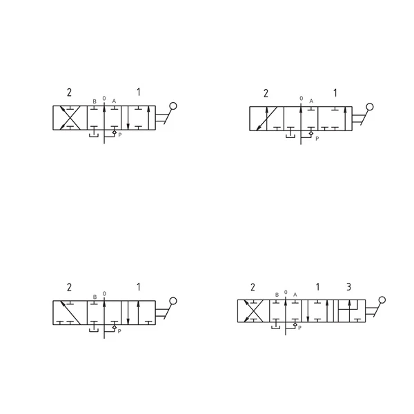
The AMI Spools represent the operational core for directional control inside hydraulic directional control valves. Designed to meet the stringent demands of industrial and mobile hydraulic circuits, these components determine the flow logic of pressurized fluid. The complete range covers a broad spectrum of applications, supporting the brand’s primary valve body families (including the AMI 3, AMI 4, AMI 21R, AMI 250, AMI 300, AMI 130, AMI 700, AMI 012, AMI 013, AMI 5C, AMI 42C, and AMI 12C series). Exact compatibility between the spool and the directional control valve is tied to the specific code, thereby ensuring optimal mechanical tolerance and the absence of undesired leakage.
The technical offering is organized into 2, 3, and 4-position models developed for single- or double-acting cylinders and actuators. In double-acting configurations (such as the base model AB1 or the AB10 series), the spool manages service ports A and B either symmetrically or asymmetrically. For single-acting applications, variants are available with exclusive service on A or B, with the opposite port plugged (e.g., AB2 and AB3) or vented to tank (e.g., AB13 and AB14). The 4-position versions introduce advanced functionalities, such as the fourth floating position (models AB4, AB4S push-to-float, AB16), essential for allowing free actuator movement under external forces.
For machine cycle optimization, spools are available in regenerative configurations (e.g., AB11, AB11A, AB11F, AB29), allowing flows to be combined to increase cylinder extension speed. Models are available for series circuits (AB10) as well as variants without transition through neutral center position (O), such as AB5 and AB24. In systems requiring smoother or progressive flow control, custom metered spool machining (option H25) can be requested, applicable to various variants (e.g., AB6P, AB7, AB8, AB9). In addition, models with inverted positions are available (e.g., 1 and 0 inverted in model AB22, or 1 and 2 inverted in AB23), providing maximum flexibility during hydraulic layout engineering.
A fundamental engineering consideration when using specific AMI Spools is the valve body architecture. As indicated by the technical specifications, installing several advanced versions (including certain regenerative, 4-position, or series-circuit models) requires the directional control valve body to be specifically pre-arranged. Furthermore, attention must be paid to compatibility matrices: directional control valve codes not highlighted for given spools indicate technical incompatibility for that specific match, making series verification prior to assembly essential.
| Feature | Value |
|---|---|
| Component Type | Spool for hydraulic directional control valves |
| Number of Positions | 2, 3, or 4 positions |
| Action Type | Single-acting, double-acting |
| Integrated Special Functions | Floating, regenerative, series circuit, inverted positions, without transition through O |
| Machining on Request | Metered spool (Option H25) |
| Installation Requirements | Pre-arranged valve body (required for specific variants marked with an asterisk) |
| Compatible Directional Control Valve Families | AMI 3, AMI 4, AMI 21R, AMI 250, AMI 300, AMI 130, AMI 700, AMI 012, AMI 013, AMI 5C, AMI 42C, AMI 12C |
| Model | Positions | Action / Circuit Type | Additional Details |
|---|---|---|---|
| AB1 | 3 Positions | Double-acting | Standard |
| AB2 | 3 Positions | Single-acting | Service on A, B plugged |
| AB3 | 3 Positions | Single-acting | Service on B, A plugged |
| AB4 | 4 Positions | Double-acting | 4th position floating |
| AB4S | 4 Positions | Double-acting | 4th position push-to-float |
| AB5 | 3 Positions | Double-acting | Without transition through O |
| AB6 | 3 Positions | Double-acting | A and B vented to tank |
| AB6P / AB7 / AB8 / AB9 | 3 Positions | Double-acting | A/B vented to tank, A vented/B locked, etc. Also metered |
| AB10 | 3 Positions | Double-acting | Series circuit |
| AB11 | 3 Positions | Double-acting | Regenerative |
| AB11A | 4 Positions | Double-acting | Regenerative in pos. 3 |
| AB11F | 4 Positions | Double-acting | Regenerative in pos. 1 |
| AB13 | 2 Positions | Single-acting | Service on A vented to tank |
| AB14 | 2 Positions | Single-acting | Service on B vented to tank |
| AB15 | 3 Positions | Double-acting | A and B vented to tank, without cross-over relief |
| AB16 | 4 Positions | Single-acting | Service on B with 4th position floating |
| AB20 | 2 Positions | N/A | pos. 1=P->B; pos. 0 P and B->T |
| AB21 | 3 Positions | Single-acting | Service on A without transition through O |
| AB22 | 3 Positions | Double-acting | Positions 1(A) and 0 inverted |
| AB23 | 3 Positions | Double-acting | Positions 1(A) and 2(B) inverted |
| AB24 | 3 Positions | Double-acting | Without transition through O, pos. 1 and 2 inverted |
| AB25 | 3 Positions | Double-acting | A and B vented to tank with positions 1 and 2 inverted |
| AB26 | 3 Positions | Double-acting | Positions 2 and 0 inverted |
| AB27 | 3 Positions | N/A | Multiple logics (P->A, P->T with A and B blocked, etc.) |
| AB28 | 3 Positions | N/A | Multiple logics, LH inlet only |
| AB29 | 3 Positions | Regenerative | Pos 1 regenerative, pos 2 P->B with A blocked |