Products

C04 Minicentraline Berarma

The C04 mini power units are equipped with variable displacement vane pumps with high operating pressure and a hydraulic-type pressure control device, allowing the delivered flow to instantly adjust according to the circuit’s demand.

Variable displacement vane pumps are positive displacement pumps; therefore, they deliver a maximum flow rate equivalent to their displacement multiplied by the rotational speed. The operating pressure is generated by the pressure losses the fluid encounters along its path through the system.

When the outlet pressure (in the system) reaches the pump’s set pressure, the delivered flow automatically adjusts to the system’s demand; once this value is reached, the pump reduces its flow rate down to zero while maintaining an almost constant pressure.

Under zero-demand conditions, the pump only delivers oil to compensate for possible leaks and pilot controls. The integration of a variable displacement vane pump and a hydraulic block enables the design of extremely compact and energy-efficient hydraulic systems in applications where pressure and/or flow control is required.

Download

Catalogs and technical documentation

BERARMA C04 MINICENTRALINE CATALOG

Description

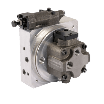
The C04 Berarma Mini Power Units are equipped with variable displacement vane pumps with high operating pressure, featuring a hydraulic pressure control device that instantly adjusts the delivered flow to the circuit’s demand.
These are positive displacement pumps that provide a maximum flow rate equivalent to displacement times rotational speed. The operating pressure is generated by pressure drops in the system. When the outlet pressure reaches the setpoint, the flow adapts to the demand, down to zero, maintaining constant pressure. In the absence of demand, the pump only delivers oil to compensate for leaks and pilot controls.

This series is designed to meet energy-saving and noise-reduction requirements in compact hydraulic systems that use fixed displacement external gear pumps. The declared advantages include:

  • Reduction of the number of components in the system

  • Reduction of electric power consumption

  • Reduction of oil heating

  • Reduction or elimination of heat exchangers

  • Significant noise reduction

Equipment and Options

  • Installation kit for main IEC motors form B14

  • Connections to standardized valve blocks (special versions available)

  • Maximum flow regulator to mechanically reduce displacement

  • Hydraulic, electric, and load-sensing control devices for flow/pressure regulation

  • Different types of seals depending on fluid and temperature

Main Technical Data

  • Maximum operating pressure: 210 bar (peaks >30% to be avoided)

  • Adjustment range: 20÷210 bar

  • Nominal displacement: 8 cm³/rev (actual 8.4 cm³/rev, ±3%)

  • Speed range: 350–2000 rpm

  • Inlet pressure: 0.8–1.5 bar absolute

  • Maximum drain pressure: 1 bar

  • Compatible hydraulic fluids: HM ISO 6743-4, HLP DIN 51524-2, HEES ISO 15380, HFD ISO 12922, HFC ISO 12922 (limitations depending on seals)

  • Operating viscosity: 22–68 cSt; at startup (open outlet) max 400 cSt

  • Minimum viscosity index: 100

  • Fluid temperature at inlet: +15 / +60 °C

  • Maximum contamination level: 20/18/15 ISO 4406 (NAS 1638 Class 9); recommended 18/16/13 ISO 4406 (NAS 1638 Class 7)

  • Weight: from 4.7 kg to 5.7 kg depending on control type

Control Types

  • S: single-stage pressure control

  • R: single-stage with remote adjustment

  • D: dual-stage adjustable pressure with 24VDC switching

  • LR: single-stage Load Sensing with remote adjustment

  • LD: dual-stage Load Sensing, 24VDC switching

Drain Configurations

  • Standard: drain connection to tank

  • Alternative: drain through external heat exchanger


Technical summary table of the main features of C04 Berarma Mini Power Units

Parameter Value
Designation / Series C04-8
Nominal displacement (ISO 3662) 8 cm³/rev
Actual displacement 8.4 cm³/rev (±3%)
Flow at 1450 rpm 12 l/min
Maximum operating pressure 210 bar
Pressure adjustment range 20 ÷ 210 bar
Maximum drain pressure 1 bar
Inlet pressure 0.8 ÷ 1.5 bar absolute
Speed range 350 ÷ 2000 rpm
Rotation direction Right-hand (clockwise viewed from shaft side)
Shaft loads No radial or axial forces
Allowed fluids HM (ISO 6743-4); HLP (DIN 51524-2); HEES (ISO 15380); HFD (ISO 12922); HFC (ISO 12922)
Seals NBR; FPM-Viton
Limits for HEES / HFD With FPM-Viton seals: Pmax 160 bar
Limits for HFC Water < 40% · NBR seals · Pmax 100 bar · Vmax 1000 rpm · T < 40°C
Operating viscosity range 22 ÷ 68 cSt (mm²/s)
Startup viscosity (open outlet) 400 cSt max
Viscosity index (ISO 2909) ≥ 100
Fluid temperature at inlet +15 ÷ +60 °C
Maximum acceptable contamination level ISO 4406: 20/18/15 · NAS 1638: Class 9
Recommended contamination level ISO 4406: 18/16/13 · NAS 1638: Class 7
Moment of inertia 0.000028 kg·m²
Pump weight (Control S) 4.7 kg
Pump weight (Control R) 5.1 kg
Pump weight (Control D) 5.4 kg
Pump weight (Control LR) 5.4 kg
Pump weight (Control LD) 5.7 kg
Available control types S · R · D · LR · LD
Coil supply (D / LD) 24 VDC · DIN 43650 type A connector
Flow regulator (max displacement) Mechanical displacement reduction
Reduced displacement per screw turn 5.3 cm³/rev
Minimum displacement Not specified (*)
Main ports Suction 3/8″ BSP Gas · Outlet “P” 1/4″ BSP Gas · Return “T” 1/4″ BSP Gas · Drain 1/4″ BSP Gas
Auxiliary ports Gauge connection 1/4″ BSP Gas · Heat exchanger outlet/return 1/4″ BSP Gas · Check valve SAE 08 seat
Control R: remote command 1/4″ BSP Gas
Controls LR / LD: Load Sensing port 1/4″ BSP Gas
IEC B14 motor connection kit M71 (X=20 mm, code 3300002071) · M80 (X=22 mm, code 3300002080) · M90 (X=32 mm, code 3300002090) · M100/M112 (X=58 mm, code 3300002100)

Brands

List of Manufacturers Brands

BERARMA

RUOTA IL DISPOSITIVO PER VISUALIZZARE CORRETTAMENTE IL SITO