The hydraulic directional control valve is the logistic heart of any hydraulic circuit. Without it, the power generated by the pump would remain unused potential, unable to move loads, activate cylinders, or regulate motors. Its primary function is to direct, interrupt, and modulate the flow of pressurized fluid toward the desired actuators, determining the actual work performed by the machine.
Ignoring proper selection and maintenance of this crucial component directly results in slow operating cycles, high energy consumption and, inevitably, premature failures. Understanding the mechanics, types, and operating principles of valves is not just a theoretical exercise but a fundamental requirement for those managing the reliability and productivity of industrial and mobile equipment.
Operational Fundamentals: The Spool and Flow Paths Principle
A hydraulic directional valve operates through the mechanical or pilot-controlled movement of a spool inside a valve body machined with extreme precision. The spool is a cylindrical rod with chamfers and grooves that, while sliding, connects or isolates internal passages (the ports) that link the pressure line (P), the tank (T), and the service lines (A and B).
We identify a valve by the number of its ports (inlets and outlets) and the number of positions the spool can take. A typical 4/3 valve, for example, manages four ports (P, T, A, B) and three positions (center, A-activated, B-activated). The center or neutral position defines the default state of the system, a critical aspect of overall safety and efficiency.
Center Position Classification: A Strategic Choice
The configuration of the center position is not arbitrary; it influences the entire dynamic behavior of the system:
- Closed Center (P, T, A, B blocked): Maximum rigidity. Locks the cylinder in position and isolates the pump and the tank. Requires a pump unloading safety device or an open-center circuit. Used for actuators that must hold load even without power.
- Open Center (P and T connected, A and B blocked): The pump unloads to the tank with minimal pressure drop. Keeps the cylinder locked, but the pump operates at near-zero pressure in the neutral position, improving energy efficiency.
- Float Center (P and A/B blocked, A/B connected to T): Ideal for systems where the actuator must move freely (float) when not commanded, while keeping the pressure line isolated.
- Pressure Block Center (P blocked, T, A, B connected): Rare. Blocks the pump but fully unloads the actuator.
Choosing the correct center not only governs motion but directly affects thermal management and pump load.
Types of Hydraulic Directional Valves and Application Areas
The choice of actuation type determines system versatility and power. Valves are classified based on their control method:
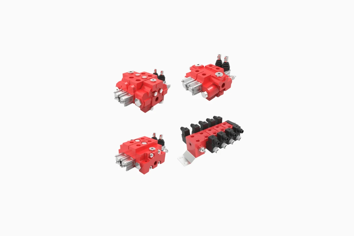
1. Manual, Mechanical and Hydraulic Operated Valves
These are the simplest types, actuated by a lever, pedal (manual), a limit switch or camshaft (mechanical), or by pilot pressure (hydraulic). They are robust, reliable and widely used in agricultural machinery, simple presses and industrial applications where human or mechanical feedback is direct.
2. Solenoid-Operated (Electrical) Valves
These represent the standard in modern automation. A solenoid (electromagnet) provides the force needed to shift the spool against spring and internal hydraulic forces.
- Direct Acting: The solenoid moves the main spool directly. Fast, compact and suitable for low flow rates (up to about 100 L/min) and high pressures.
- Pilot Operated (or Servo-Assisted): Use a small pilot valve (often solenoid-operated) to direct control pressure that shifts the larger main spool. This allows very high flow rates (hundreds or thousands of L/min) with a low-power solenoid. Response time is slightly slower, but power-handling capability is unmatched.
If you’re looking for specific components to implement or upgrade your systems, LubeTeam Hydraulic offers a complete range of advanced solutions for hydraulic directional valves.
3. Proportional Valves and Servo Valves
These components represent the pinnacle of hydraulic control, essential for machines requiring extremely precise and dynamic movements.
- Proportional Valves: The spool position is proportional to the electrical input signal (typically 0–10 V or 4–20 mA). They do not simply open or close the flow, but actively modulate it, allowing precise control of actuator speed and acceleration/deceleration ramps. Ideal for presses, machine tools and robotic applications.
- Servo Valves: Similar to proportional valves but offering superior precision and dynamics, often using closed-loop feedback control via a position transducer. Used in highly critical applications such as flight simulators, fatigue testing and nanometric precision control.
Technical Challenges: Friction, Hydraulic Forces and Reliability
Valve performance and lifespan are constantly threatened by inevitable physical phenomena. Understanding and mitigating these factors is essential for predictive maintenance.
1. Hydraulic Forces (Cross-Flow Forces)
When high-speed fluid passes through the spool orifices, it generates hydraulic forces that tend to push the spool in the direction of flow or perpendicular to it (cross forces). These forces can oppose solenoid movement or cause spool instability, especially in pilot-operated and proportional valves.
Designers balance these forces through spool geometry (compensation) or with stiffer springs. However, unexpected increases in operating pressure exacerbate the phenomenon, causing abnormal response times or, in extreme cases, spool seizure. A robust system must always include correctly set pressure relief valves upstream.
2. Contamination: The Silent Enemy
The tolerance between the spool and the valve body is minimal, often just a few microns. Fluid contamination—especially metal particles or dirt—creeps into this tight clearance, increasing static friction (stiction) and causing irregular or impossible spool movement.
- Effect: The spool does not center properly (failed return) or does not shift (stuck valve).
- Practical Solution: Using high-quality fluids and, above all, upstream filtration with extremely strict ISO 4406 cleanliness levels (often 18/16/13 or lower) drastically extends component life. Maintenance is not just “changing oil” but monitoring cleanliness with particle counters.
Fluid Overheating: Its Impact on the Valve
Hydraulic fluid overheating is both a symptom of inefficiency and a cause of degradation. Excessively hot fluid:
- Decreases Viscosity: Internal leakage (between spool and body) increases. The valve loses sealing capability, actuator speed drops, and energy is wasted as heat.
- Degrades Seals: NBR or FKM seals exposed to excessive temperatures become hard, lose elasticity and no longer seal effectively, causing internal or external leakage.
Causes and Direct Mitigation: Heat generated inside a valve is not due to useful work but to pressure losses (unnecessary throttling) and circuit configuration. For example, a closed-center valve on a fixed-displacement pump system forces the pump to unload through a relief valve, converting energy into heat unnecessarily. The solution lies in optimizing the circuit, using load-sensing systems or open-center valves whenever possible to reduce pump idle load.
Predictive Maintenance and Optimal Replacement
Modern hydraulic system management focuses on prevention, not reaction.
Monitoring: Focus on Switching Times and Current
In solenoid valves, an early sign of wear or contamination is an increase in switching time. If the time required for the solenoid to move the spool from one position to another (measured in milliseconds) begins to rise, it indicates increased internal friction. Similarly, abnormal current draw in some systems may signal a solenoid struggling to overcome a “sticking” spool (stiction).
Strategic Replacement Plan
Replacing a valve does not simply mean buying an equivalent component. It means seizing the opportunity to improve efficiency. When planning replacement, consider:
- Rated Flow and Pressure: Ensure the new valve is correctly sized for the circuit’s peak pressure, not just the average operating pressure. Oversizing is inefficient; undersizing leads to rapid failure.
- Energy Efficiency: Evaluate upgrading to pilot-operated valves with optimized pressure drops, especially for high-flow systems, reducing throttling losses and heat generation.
- Fluid Compatibility: Ensure that seals and materials of the new valve are fully compatible with the hydraulic fluid and its average operating temperature.
The hydraulic directional valve is a precision component that requires precision in its selection, installation and management. From center configuration to micron-level spool tolerance, every detail affects overall system efficiency. Investing in quality components and strict contamination-control protocols is not a cost but a key factor in maximizing reliability and productivity.