


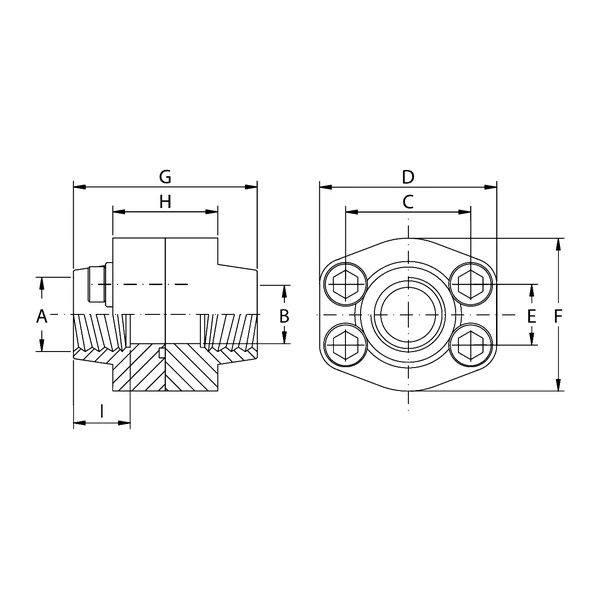
Description
Technical Specifications and Construction Standards
Oleo Tecnica BSP Threaded Double Flanges represent a high-level mechanical solution for connection and sealing in hydraulic systems operating under high pressure. Designed with BSP (Gas) threads, these flanges ensure a leak-tight connection between piping and hydraulic fluid control components, drastically reducing the risk of leakage. The range is divided into two main performance categories, Series 3000 and Series 6000, designed to cover a wide spectrum of flow rates, diameters and working pressures, meeting the most demanding requirements of industrial systems.
Materials and Mechanical Strength
The structural strength of Oleo Tecnica BSP Threaded Double Flanges is ensured by the use of high-performance metal alloys. The components are available in S355 carbon steel and, for operating environments involving corrosive fluids or specific hygiene requirements, in AISI 316L stainless steel. Together with the flange and counter flange, specific O-Rings (series from 4075 to 4537) are supplied and are essential for completing the hydraulic joint seal, fully isolating the fluid from the external environment.
Working Pressures and Dimensions (Series 3000 and Series 6000)
The maximum recommended pressure performance varies according to the Series and flange size. In Series 3000, compact models (from 1/2″ to 1″) operate safely up to 345 bar. As dimensions increase (up to 5″), recommended pressures progressively decrease, reaching nominal values such as 276 bar (1″1/4), 207 bar (from 1″1/2 to 2″) and 34 bar for 3″1/2, 4″ and 5″ diameters. Series 6000, specifically designed for severe mechanical stress, maintains a constant pressure rating of 414 bar for all available sizes, from 1/2″ up to 3″. Both series are supplied with hexagonal screw kits to ensure correct joint preload.
Ordering Designation and Fastener Specifications
The component coding system facilitates precise selection when ordering. The combination of flange, counter flange and metric screw set is identified by the codes DFS…GM or DFX…GM. Where the system standard requires imperial threads, a configuration with UNC screw sets is available, designated by the suffixes DFX…GU or DFS…GU. It is important to note that UNC screw sets are available only for carbon steel versions. Likewise, for specific models marked with an asterisk (such as DFS507G and DFS508G), the only permitted configuration uses metric carbon steel screws.
Summary technical table of the main characteristics of Oleo Tecnica BSP Threaded Double Flanges
| Feature | Value |
|---|---|
| Connection Thread | GAS / BSP |
| Available Series | Series 3000, Series 6000 |
| Max. Working Pressure (Series 3000) | From 345 bar to 34 bar (depending on size) |
| Max. Working Pressure (Series 6000) | 414 bar (constant for documented diameters) |
| Flange Sizes / Dimensions | From 1/2″ to 5″ |
| Construction Materials | S355 Steel, AISI 316L Steel |
| Metric Screw Designation | DFS…GM / DFX…GM |
| UNC Screw Designation | DFX…GU / DFS…GU (carbon steel only) |
| O-Ring Type | From model 4075 to 4537 |
Product Codes
| Product Code | Series | Size | Max. Pressure (bar) | O-Ring Type |
|---|---|---|---|---|
| DFS080G | 3000 | 1/2″ | 345 | 4075 |
| DFS080G038 | 3000 | 1/2″ (3/8″ GAS) | 345 | 4075 |
| DFS100G | 3000 | 3/4″ | 345 | 4100 |
| DFS100G012 | 3000 | 3/4″ (1/2″ GAS) | 345 | 4100 |
| DFS102G | 3000 | 1″ | 345 | 4131 |
| DFS102G034 | 3000 | 1″ (3/4″ GAS) | 345 | 4131 |
| DFS104G | 3000 | 1″1/4 | 276 | 4150 |
| DFS104G100 | 3000 | 1″1/4 (1″ GAS) | 276 | 4150 |
| DFS106G | 3000 | 1″1/2 | 207 | 4187 |
| DFS106G114 | 3000 | 1″1/2 (1″1/4 GAS) | 207 | 4187 |
| DFS108G | 3000 | 2″ | 207 | 4225 |
| DFS108G112 | 3000 | 2″ (1″1/2 GAS) | 207 | 4225 |
| DFS110G | 3000 | 2″1/2 | 172 | 4275 |
| DFS110G200 | 3000 | 2″1/2 (2″ GAS) | 173 | 4275 |
| DFS112G | 3000 | 3″ | 138 | 4337 |
| DFS112G212 | 3000 | 3″ (2″1/2 GAS) | 138 | 4337 |
| DFS114G | 3000 | 3″1/2 | 34 | 4387 |
| DFS114G300 | 3000 | 3″1/2 (3″ GAS) | 34 | 4387 |
| DFS116G | 3000 | 4″ | 34 | 4437 |
| DFS116G312 | 3000 | 4″ (3″1/2 GAS) | 34 | 4437 |
| DFS118G | 3000 | 5″ | 34 | 4537 |
| DFS401G012 | 6000 | 1/2″ | 414 | 4075 |
| DFS401G038 | 6000 | 1/2″ (3/8″ GAS) | 414 | 4075 |
| DFS402G | 6000 | 3/4″ | 414 | 4100 |
| DFS402G012 | 6000 | 3/4″ (1/2″ GAS) | 414 | 4100 |
| DFS403G | 6000 | 1″ | 414 | 4131 |
| DFS403G034 | 6000 | 1″ (3/4″ GAS) | 414 | 4131 |
| DFS404G | 6000 | 1″1/4 | 414 | 4150 |
| DFS404GL13 | 6000 | 1″1/4 (Screw variant) | 414 | 4150 |
| DFS404G100 | 6000 | 1″1/4 (1″ GAS) | 414 | 4150 |
| DFS404G100L13 | 6000 | 1″1/4 (1″ GAS – Variant) | 414 | 4150 |
| DFS405G | 6000 | 1″1/2 | 414 | 4187 |
| DFS405G114 | 6000 | 1″1/2 (1″1/4 GAS) | 414 | 4187 |
| DFS406G | 6000 | 2″ | 414 | 4225 |
| DFS406G112 | 6000 | 2″ (1″1/2 GAS) | 414 | 4225 |
| DFS507G * | 6000 | 2″1/2 | 414 | 4275 |
| DFS508G * | 6000 | 3″ | 414 | 4337 |