

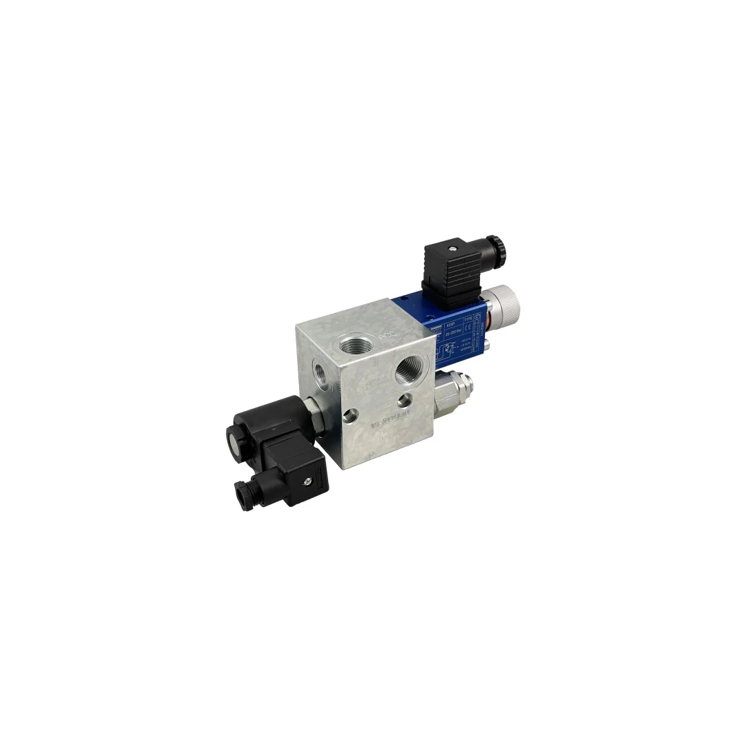
 FOX BMS1 Series Electric Discharge Block
The operation of the FOX BMS1 Series Electric Discharge Block is based on an automated electrical control system. When the preset calibration pressure is reached, the pressure switch intervenes by controlling the opening of the solenoid valve. This action diverts the pump flow toward the discharge line while simultaneously maintaining pressure inside the accumulator. Subsequently, when the pressure in the accumulator circuit decreases to the pressure switch reset value, the block intervenes again to reverse the cycle phase. The discharge passage closes, allowing the pump to restore and bring the pressure in the accumulator back up to the calibration threshold originally set on the pressure switch. To ensure accurate hydraulic control of maximum and minimum pressure values, the system supports the installation of pressure switches with adjustable hysteresis.
Construction Features and Hydraulic Connections
The block structure is designed to withstand the severe stresses typical of high-pressure hydraulic circuits. The main body is made entirely of galvanized steel, ensuring high mechanical strength and adequate surface protection. The fluid passage diameter measures 8 mm, allowing the component to handle a maximum flow rate of 50 l/min. In terms of interfaces, the block features a pressure port identified by the letter P, sized 1/2″ BSP-F, together with dedicated accumulator connections (A and A1), also sized 1/2″ BSP-F. The main discharge port, marked T, is 1/2″ BSP-F. For operational monitoring, a specific pressure gauge port (MA) of 1/4″ BSP-F is provided, while the pressure switch connections include a CETOP flange and a 1/4″ BSP-F port.
Technical Specifications and Circuit Safety
To ensure compliance and safety of the entire system, the FOX BMS1 Series Electric Discharge Block guidelines require precise configuration of the safety valve. This valve, present in the circuit, must be calibrated to a value 10% higher than the setting configured on the pressure switch. In addition, this parameter must always remain below the design pressure of the hydraulic accumulator in order to avoid operational criticalities. The supplied solenoid valve operates in the standard 24VDC version; however, a 12V version is available upon request. In terms of dimensions, the component has a width (L) of 70 mm, a height (H) of 80 mm and a depth (P) of 60 mm. The system supports a maximum pressure of 350 barg and tolerates operating temperatures ranging from a minimum of -20°C to a maximum of +80°C.