

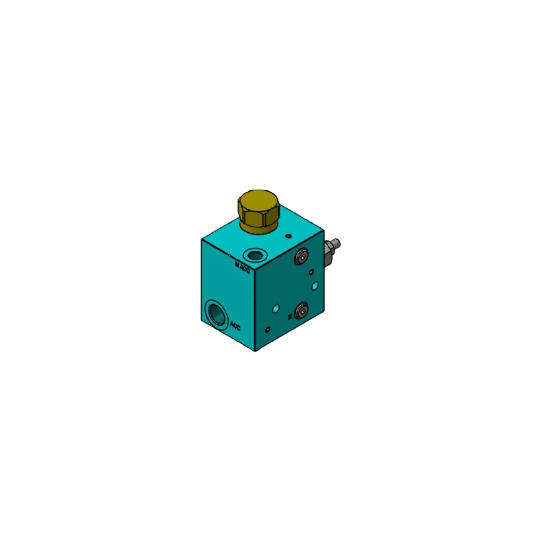
 FOX BVMS12 Series In-Line Discharge Valve
The FOX BVMS12 Series In-Line Discharge Valve represents an advanced technical solution for managing hydraulic circuits equipped with an accumulator. Specifically designed to operate directly in line, this pressure regulating valve integrates an automatic discharge function, optimizing directional control and fluid flow without requiring complex additional components or modules.
Operating Principle and Pressure Regulation
The core operation of the FOX BVMS12 Series lies in its ability to autonomously manage the loading and unloading cycles of the reference hydraulic pump. The regulation system is based on two main pressure values:
-
Calibration Pressure (P2): This is the intervention value set by the operator and is fully adjustable according to the specific and strict requirements of the hydraulic system.
-
Minimum Pressure (P1): This is a fixed parameter and cannot be adjusted during configuration. When the pressure inside the circuit reaches the set calibration value (P2), the valve immediately intervenes, placing the hydraulic pump in free discharge. This discharge condition is maintained until the minimum pressure value in the circuit (P1) drops by 15% relative to the calibration value (P2). Only when this precise differential threshold is reached does the operating cycle reset.
Accumulator Precharge Requirements (P0)
To ensure correct and safe system operation, while preserving the integrity and efficiency of the hydraulic accumulator, pressure sizing must follow a mandatory rule. The accumulator precharge pressure, identified as parameter P0, must always be calculated to be 10% lower than the minimum circuit pressure (P1).
Construction Features, Materials and Connections
From a construction standpoint, the FOX BVMS12 Series Discharge Valve is made entirely of aluminum. This choice ensures structural solidity, allowing the component to withstand a maximum operating pressure of 250 bar. A fundamental engineering advantage of this unit is the complete absence of electrical parts inside it. Since it requires no external power supply or voltage to operate, the risk of malfunctions linked to electronic issues is eliminated. In terms of interfacing, the dimensional diagrams indicate the use of standard hydraulic connections, including through ports and 1/2″ G and 1/4″ G threads, with 8.50 mm through mounting holes designed for precise anchoring.
Models and Adjustment Ranges
The BVMS12 Series range consists of five different dimensional and performance variants, each calibrated to cover a specific pressure adjustment range:
-
The BVMS12/40 model for pressures from 20 to 40 bar.
-
The BVMS12/70 model operating in the 35-70 bar range.
-
The BVMS12/140 model for pressures between 70 and 140 bar.
-
The BVMS12/210 model for medium-high applications from 105 to 210 bar.
-
The BVMS12/250 model for high peaks, with a range from 175 to 250 bar.
Technical Summary Table