 AMI dual-axis hydraulically operated joystick


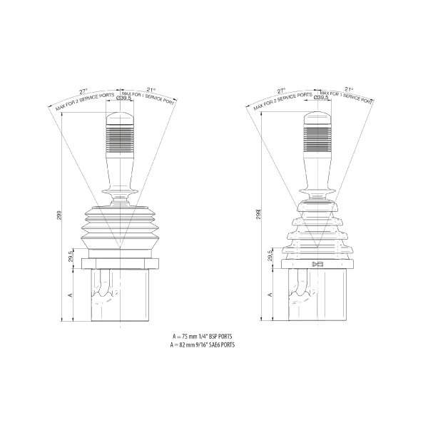
The AMI dual-axis hydraulically operated joystick stands out for a compact and standardized mechanical construction, identified by the reference model J-IDR-STD, as documented in the technical catalogue no. 205 F-3. The hydraulic pilot unit has a main control lever with an overall height of 299 mm, measured from the fastening flange plane to the top of the grip. The valve body, located below the flange, has a vertical footprint (defined as Dimension A) that varies strictly according to the type of hydraulic connections chosen for system integration. The external structure relating to the fastening plate provides various dimensional options and tolerances, with maximum footprints of Ø 110 mm, Ø 108 mm, Ø 103 mm, and Ø 100 mm. The flange is equipped with slots for mechanical installation (4 positions with size 8 or 7, and diagonal dimensions of 130 mm and 132 mm). The hydraulic connections on the lower body are arranged radially with precise center distances of 52 mm and 45° angles, optimizing space for piping.
The precision piloting of the AMI dual-axis hydraulically operated joystick is based on the mechanical actuation of the lever that governs the fluid flows directed to the service ports. The kinematic design of the control lever (“Twin axis hydraulic pilot control”) allows differentiated angular excursions based on the number of utilities activated simultaneously. Specifically, the device guarantees a maximum inclination angle of 27° when two service ports are actuated simultaneously. If the piloting requires the actuation of a single service port, the maximum excursion angle of the lever is limited by design to 21°. The diameter of the upper grip, designed for the manual management of these excursions in the hydraulic field, is 39.5 mm. The base of the lever is protected by a dedicated bellows in flexible material with a height of 29.5 mm measured above the mounting flange plane.
The fluid distribution system within the joystick uses a standardized mapping of the lower hydraulic connections. The base body is equipped with a main pressure supply port (P), a tank return port (T), and four utility ports (U1, U2, U3, U4) dedicated to controlling secondary directional control valves or actuators. The high application versatility of the J-IDR-STD series is guaranteed by the availability of two distinct configurations for the valve block, which directly determine the lower dimensional value “A”:
These two construction options allow rapid integration of the hydraulic control into multiple configurations of hydraulic circuits, ensuring full compatibility with the main fittings used in the “Fluid Contamination Control” sector and industrial hydraulic components.
| Feature | Value |
|---|---|
| Reference model | J-IDR-STD |
| Component type | Twin axis hydraulic pilot control |
| Total lever height (from flange) | 299 mm |
| Bellows base height | 29.5 mm |
| Grip diameter | 39.5 mm |
| Max. excursion (2 service ports) | 27° |
| Max. excursion (1 service port) | 21° |
| Operating connections | P, T, U1, U2, U3, U4 |
| Ports center distance (U) | 52 mm |
| Port Option 1 (Footprint A) | 1/4″ BSP (A = 75 mm) |
| Port Option 2 (Footprint A) | 9/16″ SAE6 (A = 82 mm) |
| Catalogue Reference | no. 205 F-3 |
| Model / Family | Port Configuration | Dimension A (Lower Footprint) |
|---|---|---|
| J-IDR-STD | 1/4″ BSP | 75 mm |
| J-IDR-STD | 9/16″ SAE6 | 82 mm |