 Oleo Tecnica BSP Threaded Counter Flanges


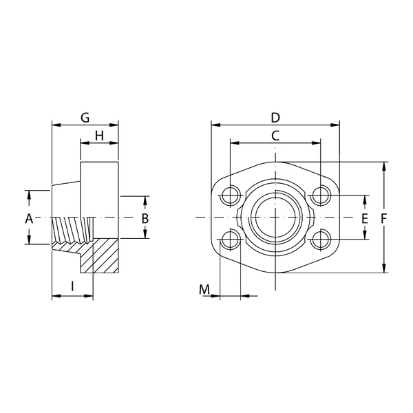
Connection components for hydraulic circuits require precise tolerances and materials suitable for withstanding constant stresses. BSP threaded counter flanges ensure high structural clamping strength. The catalogue includes variants developed in two material types: S355 steel and AISI 316L stainless steel, allowing selection according to the aggressiveness of the working environment or specific fluid contamination control requirements.
The ordering designation follows a strict nomenclature to immediately identify construction specifications. Standard versions in S355 material with metric threaded fastening holes are identified by the prefix “GFS…G”, while variants with UNC holes are classified as “GFS…GU”. For AISI 316L stainless steel versions, the system uses the prefixes “GFX…G” (metric) and “GFX…GU” (UNC). This flexibility allows integration into systems based on both international and imperial standards.
Sealing performance is directly related to the selected series and nominal size of the counter flange.
In Series 3000, the maximum recommended working pressure varies according to size. For smaller sizes, such as 1/2″, 3/4″ and 1″, the system withstands hydraulic loads up to 345 Kg/cm². As the cross-section increases, the operating limits progressively decrease, from 276 Kg/cm² for 1″1/4 sizes to 207 Kg/cm² (1″1/2 and 2″), down to 138 Kg/cm² for 3″ formats and the 3″1/2, 4″ and 5″ size classes.
Series 6000, on the other hand, is engineered for extremely high pressures. In this category, regardless of size (ranging from a minimum of 1/2″ up to 3″), the entire range maintains a constant maximum recommended working pressure of 414 Kg/cm², providing an exceptional safety margin for heavy-duty hydraulic systems or systems subject to frequent pressure peaks.
The geometric architecture of the flange ensures stable planar coupling. The dimensional specifications cover wide centre-distance ranges to ensure perfect installation on threaded ports. The weight of individual components ranges from 0.26 kg for the basic Series 3000 models up to 11.8 kg for the robust 3″ Series 6000 GFS508G, confirming the use of metal sections suitable for mechanical stress. These fittings are naturally suited for applications in heavy industry, earthmoving machinery and any hydraulic system architecture in which the containment of high-pressure fluids is an essential design requirement.
| Feature | Value |
|---|---|
| Thread Type | BSP |
| Reference Series | Series 3000 / Series 6000 |
| Construction Materials | S355 / AISI 316L Stainless Steel |
| Fastening Holes | Metric / UNC |
| Max. Pressure (Series 3000) | From 138 Kg/cm² to 345 Kg/cm² |
| Max. Pressure (Series 6000) | 414 Kg/cm² (constant throughout the range) |
| Size Range (Series 3000) | From 1/2″ to 5″ |
| Size Range (Series 6000) | From 1/2″ to 3″ |
| Model (S355 Metric Base) | Series | Size (BSP) | Max. Pressure (Kg/cm²) | Weight (Kg) |
|---|---|---|---|---|
| GFS080G | 3000 | 1/2″ | 345 | 0.26 |
| GFS080G038 | 3000 | 3/8″ | 345 | 0.28 |
| GFS100G | 3000 | 3/4″ | 345 | 0.41 |
| GFS100G012 | 3000 | 1/2″ | 345 | 0.44 |
| GFS102G | 3000 | 1″ | 345 | 0.49 |
| GFS102G034 | 3000 | 3/4″ | 345 | 0.55 |
| GFS104G | 3000 | 1″1/4 | 276 | 0.71 |
| GFS104G100 | 3000 | 1″ | 276 | 0.85 |
| GFS106G | 3000 | 1″1/2 | 207 | 1.12 |
| GFS106G114 | 3000 | 1″1/4 | 207 | 1.24 |
| GFS108G | 3000 | 2″ | 207 | 1.24 |
| GFS108G112 | 3000 | 1″1/2 | 207 | 1.59 |
| GFS110G | 3000 | 2″1/2 | 172 | 1.66 |
| GFS110G200 | 3000 | 2″ | 173 | 2.20 |
| GFS112G | 3000 | 3″ | 138 | 2.37 |
| GFS112G212 | 3000 | 2″1/2 | 138 | 2.65 |
| GFS114G | 3000 | 3″1/2 | – | 2.51 |
| GFS114G300 | 3000 | 3″ | – | 3.37 |
| GFS116G | 3000 | 4″ | – | 2.87 |
| GFS116G312 | 3000 | 3″1/2 | – | 3.39 |
| GFS118G | 3000 | 5″ | – | 5.80 |
| GFS401G012 | 6000 | 1/2″ | 414 | 0.26 |
| GFS401G038 | 6000 | 3/8″ | 414 | 0.29 |
| GFS402G | 6000 | 3/4″ | 414 | 0.55 |
| GFS402G012 | 6000 | 1/2″ | 414 | 0.60 |
| GFS403G | 6000 | 1″ | 414 | 0.87 |
| GFS403G034 | 6000 | 3/4″ | 414 | 0.9 |
| GFS404G | 6000 | 1″1/4 | 414 | 1.21 |
| GFS404G100 | 6000 | 1″ | 414 | 1.34 |
| GFS405G | 6000 | 1″1/2 | 414 | 1.90 |
| GFS405G114 | 6000 | 1″1/4 | 414 | 2.03 |
| GFS406G | 6000 | 2″ | 414 | 3.43 |
| GFS406G112 | 6000 | 1″1/2 | 414 | 3.92 |
| GFS507G | 6000 | 2″1/2 | 414 | 7.25 |
| GFS508G | 6000 | 3″ | 414 | 11.8 |