


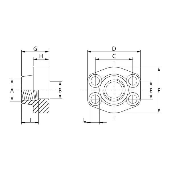
Description
Construction Specifications and Working Pressures
Oleo Tecnica BSP Threaded Flanges are divided into two main categories: Series 3000 and Series 6000, both designed to meet demanding sealing requirements in hydraulic circuits. All catalogue variants feature an internal GAS (BSP) thread, ensuring a standardised and reliable connection with system fittings.
For Series 3000, the maximum recommended working pressure decreases as the nominal flange size increases. Compact 1/2″ and 3/4″ models reach a pressure rating of 345 Kg/cm². As the diameter increases, the supported pressure varies: 1″1/4 sizes support up to 276 Kg/cm², 1″1/2 and 2″ versions are rated at 207 Kg/cm², 2″1/2 models at 172 Kg/cm², and 3″ models at 138 Kg/cm², decreasing to 34 Kg/cm² for the largest flanges (3″1/2, 4″ and 5″).
Series 6000, engineered for heavy-duty, very high-pressure hydraulic applications, instead provides a constant pressure rating of 414 Kg/cm² across all available sizes, ranging from 1/2″ up to 3″.
Materials and Performance
To suit both standard operating environments and highly corrosive conditions, Oleo Tecnica BSP Threaded Flanges are manufactured using two specific metal alloys. The standard version uses S355 carbon steel, which is well suited to most heavy industrial applications. Where the application requires greater chemical and oxidation resistance, the entire range can be manufactured on request in AISI 316L stainless steel.
Ordering Designation and Assembly Kits
The coding-system architecture allows the purchasing department to configure the supply quickly. The code prefix defines the material: “AFS” identifies products in S355 steel, while “AFX” indicates the use of AISI 316L stainless steel.
The system provides three supply options:
- Flange Only (suffix “…G”): Bare flange body.
- Complete Metric Flange (suffix “…GM”): Includes the flange body, metric screw set, spring washers and sealing O-ring.
- Complete UNC Flange (suffix “…GU”): Includes the flange, UNC threaded screws, spring washers and O-ring.
From a technical standpoint, sets with UNC screws are supplied exclusively in carbon steel. In addition, specific structural components, such as the Series 6000 AFS508G flange, are available with screw sets only in metric thread and exclusively in carbon steel.
Dimensional Parameters and Structural Weights
The dimensional tables define the exact parameters required for mechanical coupling. All flanges include a seat for specific leak-tight O-rings; the range extends from type 4075 for compact 1/2″ versions up to O-ring 4537 used on the 5″ Series 3000 model. Component weight also reflects the industrial nature of the product, starting from 0.25 kg for the smallest sizes (such as AFS080G) and reaching a maximum of 11.2 kg for the very high-pressure 3″ AFS508G model. These data provide designers with the parameters required for safe machine installation.
Summary technical table of the main characteristics of Oleo Tecnica BSP Threaded Flanges.
| Feature | Value |
|---|---|
| Available Series | Series 3000 / Series 6000 |
| Thread Type | GAS (BSP) |
| Max. Working Pressure (Series 3000) | From 34 Kg/cm² to 345 Kg/cm² (depending on size) |
| Max. Working Pressure (Series 6000) | 414 Kg/cm² |
| Sizes (Series 3000) | From 1/2″ to 5″ |
| Sizes (Series 6000) | From 1/2″ to 3″ |
| Construction Materials | S355 Carbon Steel / AISI 316L Stainless Steel |
| Assembly Kit Components (…GM / …GU) | Flange, screws (metric or UNC), spring washers, O-ring |
Product Codes
| Base Flange Model (S355) | Series | Size / Thread Type | Max. Pressure (Kg/cm²) |
|---|---|---|---|
| AFS080G | 3000 | 1/2″ GAS | 345 |
| AFS080G038 | 3000 | 3/8″ GAS on 1/2″ flange | 345 |
| AFS100G | 3000 | 3/4″ GAS | 345 |
| AFS100G012 | 3000 | 1/2″ GAS on 3/4″ flange | 345 |
| AFS102G | 3000 | 1″ GAS | 345 |
| AFS102G034 | 3000 | 3/4″ GAS on 1″ flange | 345 |
| AFS104G | 3000 | 1″1/4 GAS | 276 |
| AFS104GL13 | 3000 | 1″1/4 GAS | 276 |
| AFS104G100 | 3000 | 1″ GAS on 1″1/4 flange | 276 |
| AFS106G | 3000 | 1″1/2 GAS | 207 |
| AFS106G114 | 3000 | 1″1/4 GAS on 1″1/2 flange | 207 |
| AFS108G | 3000 | 2″ GAS | 207 |
| AFS108G112 | 3000 | 1″1/2 GAS on 2″ flange | 207 |
| AFS110G | 3000 | 2″1/2 GAS | 172 |
| AFS110G200 | 3000 | 2″ GAS on 2″1/2 flange | 173 |
| AFS112G | 3000 | 3″ GAS | 138 |
| AFS112G212 | 3000 | 2″1/2 GAS on 3″ flange | 138 |
| AFS114G | 3000 | 3″1/2 GAS | 34 |
| AFS114G300 | 3000 | 3″ GAS on 3″1/2 flange | 34 |
| AFS116G | 3000 | 4″ GAS | 34 |
| AFS116G312 | 3000 | 3″1/2 GAS on 4″ flange | 34 |
| AFS118G | 3000 | 5″ GAS | 34 |
| AFS401G012 | 6000 | 1/2″ GAS | 414 |
| AFS401G038 | 6000 | 3/8″ GAS on 1/2″ flange | 414 |
| AFS402G | 6000 | 3/4″ GAS | 414 |
| AFS402G012 | 6000 | 1/2″ GAS on 3/4″ flange | 414 |
| AFS403G | 6000 | 1″ GAS | 414 |
| AFS403G034 | 6000 | 3/4″ GAS on 1″ flange | 414 |
| AFS404G | 6000 | 1″1/4 GAS | 414 |
| AFS404GL13 | 6000 | 1″1/4 GAS | 414 |
| AFS404G100 | 6000 | 1″ GAS on 1″1/4 flange | 414 |
| AFS404G100L13 | 6000 | 1″ GAS on 1″1/4 flange | 414 |
| AFS405G | 6000 | 1″1/2 GAS | 414 |
| AFS405G114 | 6000 | 1″1/4 GAS on 1″1/2 flange | 414 |
| AFS406G | 6000 | 2″ GAS | 414 |
| AFS406G112 | 6000 | 1″1/2 GAS on 2″ flange | 414 |
| AFS507G | 6000 | 2″1/2 GAS | 414 |
| AFS508G | 6000 | 3″ GAS | 414 |