


Description
Construction and Mechanical Features
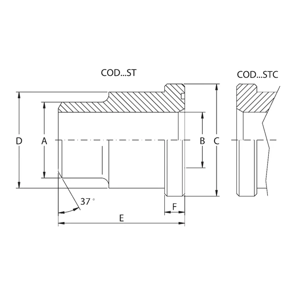
Oleo Tecnica CETOP Butt-Weld Stubs are key components for creating leak-tight, deformation-resistant flanged joints on medium- and high-pressure hydraulic lines. Precision machining includes preparation of the joint edge with a calibrated 37° bevel, ideal for full-penetration butt welding on metal pipes ranging from 3/8″ up to 4″.
The product range includes two main material options:
- Forged A105 carbon steel (or equivalent), suitable for standard industrial applications with conventional fluids;
- AISI 316L austenitic stainless steel, designed to provide maximum chemical compatibility and high corrosion resistance in aggressive environments.
The components can be ordered with a front profile featuring an O-Ring groove or with a flat face without an O-Ring seat, allowing flanged coupling in compliance with CETOP dimensional requirements.
Working Pressures and Strength Classes
The Oleo Tecnica catalogue divides the butt-weld stubs into two standardized pressure series:
- Series 250: maximum recommended working pressure of 250 Bar, available in nominal sizes from 3/8″ to 4″;
- Series 400: maximum recommended working pressure of 400 Bar, designed for heavy-duty hydraulic circuits with a size range from 3/8″ to 4″.
The maximum recommended working pressure is based on the technical parameters of the matching clamping flange. The actual maximum working pressure of the entire system is nevertheless determined by the wall thickness and metallurgical quality of the welded pipe steel.
O-Ring Seals
Models with a front groove accommodate specific O-Ring seals for each nominal size. In Series 250, the elastomeric sealing range includes standard O-Ring codes from 3068 up to 4387, as well as a specific 4″ version with the larger OR6387 seal. In Series 400, due to higher hydraulic loads, standard seals from OR 3068 to OR 4337 are used, together with special larger configurations: OR6275 on the 2″1/2 size, OR6300 on the 3″ size and OR6350 on the 4″ version.
Ordering Designation and Variants
The unique Oleo Tecnica coding system allows the required system variants to be configured precisely:
- COD…ST: A105 carbon steel version or equivalent, with O-Ring seat;
- COD…STC: A105 carbon steel version or equivalent, without O-Ring seat;
- CODX…ST: AISI 316L stainless steel version, with O-Ring seat;
- CODX…STC: AISI 316L stainless steel version, without O-Ring seat.
Technical Summary Table of the Main Characteristics of Oleo Tecnica CETOP Butt-Weld Stubs.
| Characteristic | Value |
|---|---|
| Interface Standard | CETOP |
| Welding Type | Butt weld (37° bevel) |
| Available Pressure Series | Series 250 (250 Bar) / Series 400 (400 Bar) |
| Construction Materials | A105 steel or equivalent / AISI 316L stainless steel |
| Front Sealing Configurations | With O-Ring seat (…ST) / Without O-Ring seat (…STC) |
| Nominal Size Range | From 3/8″ to 4″ |
| Pressure Limiting Factor | Based on the flange; working pressure determined by pipe thickness and material |
Product Codes
| Series | Max Pressure (Bar) | Size | Type Code (A105 with OR Seat) | Dim. A (mm) | Dim. B (mm) | Dim. C (mm) | Dim. D (mm) | Dim. E (mm) | Dim. F (mm) | O-Ring Type | Weight (kg) |
|---|---|---|---|---|---|---|---|---|---|---|---|
| Series 250 | 250 | 3/8″ | COD38ST250 | 18 | 12,5 | 24,5 | 18 | 30 | 7,3 | 3068 | 0,05 |
| Series 250 | 250 | 1/2″ | COD12ST250 | 22 | 15 | 30,2 | 24 | 30 | 7,3 | 4075 | 0,07 |
| Series 250 | 250 | 3/4″ | COD34ST250 | 28 | 20 | 38,1 | 31,5 | 35 | 7,3 | 4100 | 0,13 |
| Series 250 | 250 | 1″ | COD1ST250 | 35 | 25 | 44,4 | 38 | 40 | 8,6 | 4131 | 0,21 |
| Series 250 | 250 | 1″1/4 | COD114ST250 | 43 | 32 | 50,8 | 43 | 45 | 8,6 | 4150 | 0,27 |
| Series 250 | 250 | 1″1/2 | COD112ST250 | 50 | 38 | 60,3 | 50 | 50 | 8,6 | 4187 | 0,39 |
| Series 250 | 250 | 2″ | COD2ST250 | 62 | 47 | 71,4 | 62 | 60 | 10,6 | 4225 | 0,69 |
| Series 250 | 250 | 2″1/2 | COD212ST250 | 76 | 58 | 87,2 | 76 | 70 | 10,6 | 4275 | 1,16 |
| Series 250 | 250 | 3″ | COD3ST250 | 90 | 70 | 101,6 | 90 | 80 | 10,6 | 4337 | 1,73 |
| Series 250 | 250 | 3″1/2 | COD312ST250 | 102 | 80 | 119,0 | 102 | 90 | 19,0 | 4337 | 2,67 |
| Series 250 | 250 | 4″ | COD4ST250 | 114 | 90 | 131,0 | 114 | 105 | 22,5 | 4387 | 3,75 |
| Series 250 | 250 | 4″ | COD4ST250 OR6387 | 114 | 90 | 131,0 | 114 | 105 | 22,5 | 6387 | 3,75 |
| Series 400 | 400 | 3/8″ | COD38ST400 | 18 | 11 | 26,0 | 18 | 35 | 8,4 | 3068 | 0,07 |
| Series 400 | 400 | 1/2″ | COD12ST400 | 22 | 14 | 31,8 | 24 | 40 | 8,4 | 4075 | 0,11 |
| Series 400 | 400 | 3/4″ | COD34ST400 | 28 | 18 | 39,5 | 32 | 45 | 9,4 | 4100 | 0,20 |
| Series 400 | 400 | 1″ | COD1ST400 | 35 | 22 | 47,6 | 38 | 50 | 10,1 | 4131 | 0,32 |
| Series 400 | 400 | 1″1/4 | COD114ST400 | 44 | 29 | 54,0 | 44 | 55 | 10,9 | 4150 | 0,44 |
| Series 400 | 400 | 1″1/2 | COD112ST400 | 51 | 35 | 63,5 | 51 | 60 | 13,2 | 4187 | 0,63 |
| Series 400 | 400 | 2″ | COD2ST400 | 61 | 43 | 79,4 | 67 | 70 | 13,7 | 4225 | 1,21 |
| Series 400 | 400 | 2″1/2 | COD212ST400 | 80 | 53 | 94,2 | 80 | 80 | 17,6 | 4275 | 2,04 |
| Series 400 | 400 | 2″1/2 | COD212ST400 OR6275 | 80 | 53 | 94,2 | 80 | 80 | 17,6 | 6275 | 2,04 |
| Series 400 | 400 | 3″ | COD3ST400 | 90 | 58 | 104,0 | 90 | 90 | 17,6 | 4275 | 2,93 |
| Series 400 | 400 | 3″ | COD3ST400 OR6300 | 90 | 58 | 104,0 | 90 | 90 | 17,6 | 6300 | 2,93 |
| Series 400 | 400 | 3″1/2 | COD312ST400 | 102 | 63 | 119,0 | 102 | 90 | 19,0 | 4275 | 4,00 |
| Series 400 | 400 | 4″ | COD4ST400 | 114 | 74 | 131,0 | 114 | 105 | 22,5 | 4337 | 5,45 |
| Series 400 | 400 | 4″ | COD4ST400 OR6350 | 114 | 74 | 131,0 | 114 | 105 | 22,5 | 6350 | 5,45 |