


In hydraulic systems, the connection between the motor and the pump plays a fundamental role in transferring the mechanical energy required for system operation. The quality of this connection affects the reliability of the motor-pump assembly, operational continuity, and the service life of the components involved.
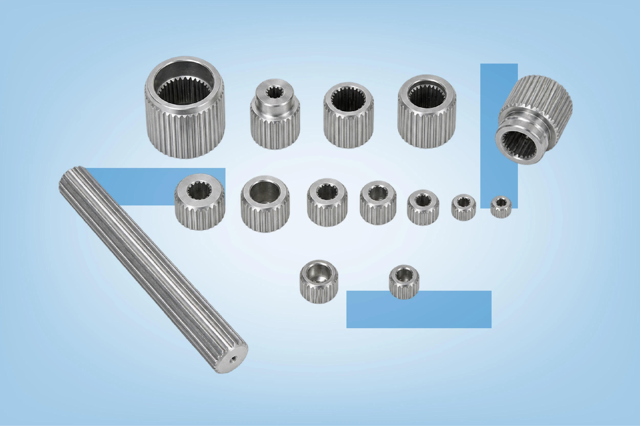
Splined half couplings for hydraulic pumps provide a mechanical connection with splined shafts through a geometry that transmits torque via contact between corresponding teeth and grooves.
Incorrect component selection can compromise power transmission, accelerate wear on contact surfaces, and increase the risk of failure. For this reason, choosing the right component requires careful consideration of dimensional characteristics, load conditions, and system configuration.
The Role of Splined Half Couplings in Hydraulic Systems
How the Connection Between Motor and Pump Works
A hydraulic motor-pump assembly consists of a motor, generally electric, and a pump that converts the mechanical energy it receives into hydraulic energy.
The motor generates rotational motion and transfers it to the pump shaft through a coupling system. The pump uses this motion to circulate the hydraulic fluid and generate the flow required for system operation. Pressure develops according to the resistance encountered by the fluid within the circuit.
The coupling system must transmit the torque required by the pump without introducing stresses that exceed the specifications of the components.
The splined half coupling is one of the components that can contribute to this transmission. Its internal geometry enables engagement with a compatible splined shaft, transferring torque through contact between the corresponding profiles.
What Makes a Splined Half Coupling Different
Unlike a connection using a cylindrical shaft and key, a splined connection features a series of teeth distributed around the circumference of the shaft.
When properly designed and sized, this configuration offers several advantages:
- It transmits torque through multiple contact surfaces.
- It provides a mechanical connection defined by the geometry of the profiles.
- It can facilitate centering when the system incorporates suitable surfaces and tolerances.
- It meets the requirements of numerous industrial power transmission configurations.
A splined half coupling does not necessarily constitute a complete coupling. In many applications, it represents one of the hubs within a coupling system, which may include additional components to connect the two shafts.
This distinction is important because the performance of the entire transmission system also depends on the coupling type, any flexible elements, and installation conditions.
Torque Transmission and Characteristics of Splined Connections
How Splines Transmit Rotational Motion
When the motor drives the system, the tooth surfaces of the shaft exert force on the corresponding surfaces of the half coupling. This contact transfers torque to the next component in the transmission system.
The principle resembles the engagement between two toothed components: their geometry prevents unrestricted relative rotation and enables the transfer of rotational motion.
However, the actual load distribution is not always uniform across all teeth. Dimensional tolerances, geometric inaccuracies, and deformation under load can concentrate stresses on certain surfaces.
For this reason, the number of splines alone does not determine torque transmission capacity. The profile, material, effective engagement length, and operating conditions must also be considered.
The Importance of Transmitted Torque
Torque represents the rotational force that the motor transfers to the pump.
In a hydraulic system, the required torque mainly depends on pump displacement, operating pressure, and mechanical efficiency. As the pressure required by the circuit increases, the torque needed to drive the pump generally increases as well.
Designers must therefore ensure that the mechanical connection can withstand not only normal operating conditions but also the most demanding conditions expected during service.
Frequent starts, sudden load variations, and pressure peaks can subject the transmission system to stresses greater than those experienced during normal operation.
Proper sizing takes these conditions into account and keeps loads within the limits specified by the manufacturers.
How to Choose Splined Half Couplings for Hydraulic Pumps
Compatibility Between Spline Profile and Shaft
The first step is to verify the geometric compatibility between the half coupling and the shaft.
Two components may have apparently similar external dimensions without being compatible. The spline profile requires an exact match between several parameters:
- Number of teeth.
- Characteristic diameters.
- Shape and dimensions of the splines.
- Profile module or pitch, where applicable.
- Pressure angle, where relevant.
- Fit tolerances.
- Effective engagement length.
Reference to the applicable dimensional standard makes it possible to identify the required geometry correctly.
Parallel-sided splines and involute splines, for example, follow different geometric principles and are not interchangeable simply because they have similar diameters.
Before purchasing, technicians must compare the half coupling specifications with those of the pump shaft or the component to which it must be connected.
Materials and Resistance to Mechanical Stress
The material of the half coupling contributes to its ability to withstand mechanical loads and wear.
Key characteristics to evaluate include mechanical strength, surface hardness, and behavior under repeated loading.
In particular, cyclic stresses can promote fatigue when the component operates beyond its specified limits or experiences stress concentrations.
Surface treatments, where present, can also affect the wear resistance of the splines.
However, no single material is universally superior. The choice depends on the required torque, geometry, frequency of operating cycles, and manufacturer recommendations.
Dimensions and Configuration of the Motor-Pump Assembly
Half coupling compatibility involves more than just the internal profile.
Axial and radial dimensions, component positioning, available shaft length, and interaction with other transmission elements must also be verified.
A component that is geometrically compatible with the shaft may still be unsuitable for the overall configuration of the motor-pump assembly.
Component selection should therefore begin with the technical drawing of the complete assembly rather than the dimensions of the individual part alone.
To identify available solutions, consult the Splined Half Couplings section of the LubeTeam Hydraulic catalog and compare component characteristics with the requirements of the application.
Installing Splined Half Couplings: Technical Checks and Best Practices
Inspecting Surfaces Before Installation
Before installation, technicians must inspect the condition of the splines on both the shaft and the half coupling.
Impact damage, deformation, corrosion, and metal debris can interfere with engagement and compromise proper contact between surfaces.
The inspection should include checking for burrs, verifying tooth integrity, and ensuring surface cleanliness. Existing signs of wear must also be examined, particularly when replacing components in machinery that has already been in operation.
Operators should avoid forcing the connection through impacts or pressure not specified by the manufacturer. Forced assembly can damage the profiles and introduce unwanted stresses.
The component’s technical instructions specify the correct installation procedures and any lubrication requirements.
Alignment Between Motor and Pump
Shaft alignment is one of the most important aspects of building a reliable motor-pump assembly.
Misalignment can generate additional loads on bearings, increase vibration, and accelerate wear on transmission components.
Three conditions must be distinguished:
- Radial misalignment: the shaft axes are parallel but do not coincide.
- Angular misalignment: the shaft axes are inclined relative to each other.
- Axial positioning error: the distance between components does not comply with the specified dimensions.
Technicians can use dial indicators or laser alignment systems to verify the relative position of the shafts, depending on the machine configuration.
A flexible coupling can compensate for certain misalignments within the limits specified by the manufacturer. A splined half coupling alone does not guarantee this capability.
The correct installation procedure must comply with the tolerances of the entire coupling system.
Checks Before Start-Up
After installation, maintenance technicians must verify the correct positioning of the half coupling, the fastening of all required elements, and the absence of mechanical interference.
Where the configuration allows, manually checking rotation with the machine isolated from all energy sources can help identify potential obstructions.
Before start-up, operators must also restore protective guards around rotating components and verify compliance with safety procedures.
During the initial operating stages, unusual noises, vibrations, and temperature variations may indicate installation problems or incorrect operating conditions.
Splined Half Coupling Wear: Causes and Warning Signs
Excessive Clearance and Tooth Deterioration
Over time, spline surfaces can experience wear.
Repeated contact between profiles, particularly in the presence of relative micromovements, can progressively alter tooth geometry.
Clearance exceeding the specified limits can cause impacts between surfaces during torque variations and accelerate deterioration of the connection.
Warning signs include increased torsional backlash, the presence of metal particles, changes in tooth profiles, and unusual noises during load variations.
These symptoms require inspection of the entire connection, as wear may affect both the half coupling and the corresponding shaft.
Fretting and Micromovements in Splined Connections
Fretting is a specific form of surface damage that occurs when contacting surfaces experience repeated small-amplitude relative movements.
In splined connections, vibrations and load variations can promote these micromovements.
This phenomenon can generate wear particles and, under certain conditions, oxides that appear reddish or dark.
The presence of these residues may indicate deterioration, but a thorough inspection is necessary to identify the actual cause.
To limit the problem, technicians must verify dimensional compatibility, loading conditions, alignment, and lubrication requirements.
Overloads and Mechanical Damage
A torque peak exceeding the connection’s capacity can cause permanent deformation or failure.
Possible causes include sudden pump seizure, abnormal pressure conditions, demanding start-ups, and inadequate component sizing.
Even a connection that operates correctly under nominal conditions may prove unsuitable when the system experiences frequent overloads.
In these cases, replacing the half coupling without identifying the source of the excessive stresses risks causing the same failure again.
Splined Half Coupling Maintenance and Failure Prevention
Periodic Inspection of Mechanical Connections
Preventive maintenance must consider the transmission system as a whole.
During scheduled maintenance, technicians can inspect fasteners, check for abnormal clearance, assess the integrity of accessible surfaces, and examine the condition of any flexible coupling elements.
When inspection requires disassembly, the condition of the splines must be compared with manufacturer specifications, and any deformation or signs of wear must be assessed.
Inspection frequency depends on operating intensity, environmental conditions, and the criticality of the system.
Vibration Monitoring and Condition-Based Maintenance
Vibration monitoring can help identify abnormalities in the motor-pump assembly before they cause unplanned downtime.
Increased vibration may result from misalignment, bearing problems, rotating imbalances, or deterioration of transmission components.
However, vibration measurements alone do not necessarily identify a splined half coupling failure. Technicians must interpret the results alongside other operating parameters and perform direct inspections when necessary.
Comparing measurements with values recorded during normal operation helps identify significant changes and schedule targeted inspections.
Splined Half Couplings and Motor-Pump Assembly Reliability
A properly sized mechanical connection contributes to stable torque transmission and helps limit unwanted stresses on rotating components.
Half coupling selection must therefore consider geometric compatibility, load capacity, operating conditions, and the characteristics of the entire coupling system.
Installation and maintenance also play a decisive role. Dimensional checks, accurate alignment, and periodic inspections help identify conditions that could compromise component service life.
For technicians, designers, and maintenance managers, selecting the correct splined half couplings means addressing an essential element of hydraulic system operational continuity, reducing the risk of premature wear and transmission failures.